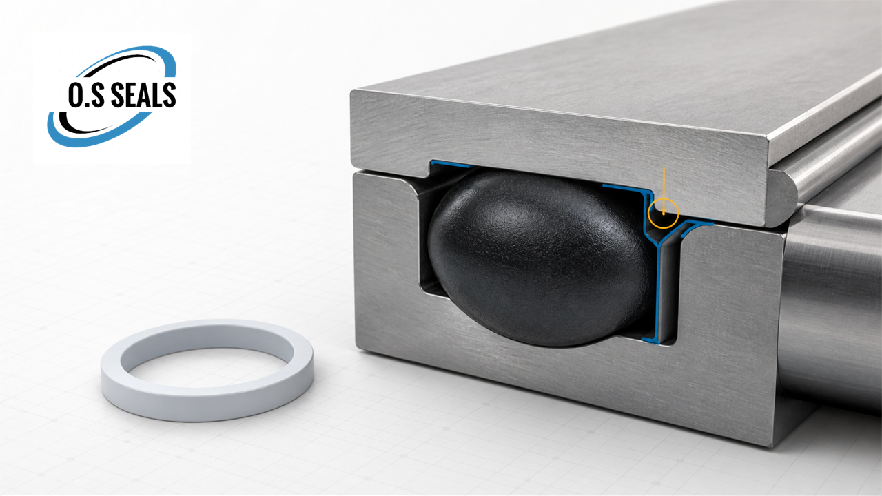
O-Ring extrusion occurs when pressure forces part of the elastomer into the clearance between mating hardware. The unsupported material can then be pinched, shaved or repeatedly damaged. A failed seal may show nibbled edges, small missing pieces, a thin flap of rubber or damage concentrated on the low-pressure side.
It is tempting to treat this as a simple material problem. In practice, extrusion is usually a system-level issue. Pressure, extrusion gap, groove dimensions, hardware movement, temperature, compound properties and pressure cycling all contribute. Replacing the failed O-Ring with a harder compound may improve resistance, but it does not automatically correct an oversized or changing gap.
For industrial buyers, the purchasing risk is equally important. If an RFQ only lists the O-Ring size and material, suppliers may quote the same part while assuming very different service conditions. A reliable review starts with the application and the complete sealing geometry.
1. Understand What O-Ring Extrusion Looks Like
Extrusion damage is commonly found at the side of the O-Ring facing the clearance gap. Under pressure, the seal moves toward the low-pressure side. If the gap is large enough, the elastomer begins to enter it. Pressure cycling can push and pull the material repeatedly until the edge becomes ragged or pieces separate.
The appearance may resemble installation cuts, abrasion or chemical deterioration, so the failure location matters. Installation damage often follows the path of a sharp edge, thread or port. Abrasion normally creates broader wear in a dynamic contact area. Chemical attack may cause swelling, softening, cracking or loss of properties across more of the seal.
A useful failure review should record the damaged side, pressure direction, groove position and orientation before the seal is cleaned or discarded. Photographs of the installed location and the removed part provide better evidence than a loose O-Ring photographed without context.
2. Pressure Is Only One Part of the Risk
Higher pressure increases the force pushing the O-Ring toward the gap, but a single pressure value is not enough to predict performance. The design review should distinguish normal working pressure, maximum continuous pressure, short pressure peaks and test pressure.
Pressure direction also matters. In one-directional service, a backup ring can support the low-pressure side. In reversing pressure, support may be required on both sides. If this detail is missing from the drawing or RFQ, a technically correct part can still be installed in the wrong arrangement.
Pressure cycling adds fatigue. A seal that survives steady pressure may deteriorate when the system repeatedly starts, stops or changes direction. Rapid decompression creates another risk: gas or pressurized fluid absorbed by the elastomer may expand faster than it can escape, producing internal damage that should not be confused with ordinary gap extrusion.
Buyers should therefore communicate the pressure profile, not only the nominal rating of the equipment.
3. Measure the Maximum Extrusion Gap
The critical clearance is the maximum gap that exists under the worst combination of manufacturing tolerance, pressure, temperature, wear and hardware movement. Checking only the nominal drawing dimension can underestimate the real unsupported space.
In a piston or rod assembly, the effective gap may change because of diametrical clearance, side loading, bearing wear, eccentricity or elastic deformation under pressure. In static flanges, bolt loading and component deflection can also change the local gap.
The following information should be reviewed together:
– groove diameter, width and depth;
– mating component dimensions and tolerances;
– maximum diametrical or radial clearance;
– hardware material and possible deformation;
– wear allowance during service;
– surface defects, chamfers and edge condition near the gap.
This is why a generic statement such as “suitable for high pressure” is not a complete specification. The allowable pressure depends strongly on the actual gap, temperature, material and motion.
4. Evaluate Material, Hardness and Temperature Together
Harder elastomers generally resist extrusion better because they deform less easily into a clearance. However, hardness cannot be selected in isolation.
A harder O-Ring may require more installation force, conform less effectively to surface variation and behave differently at low temperature. If the compound is incompatible with the fluid, increasing hardness does not solve swelling or property loss. At elevated temperature, the elastomer can soften and its mechanical strength can decrease, reducing extrusion resistance even when room-temperature hardness appears acceptable.
Material selection should therefore consider:
– fluid or gas compatibility;
– continuous and peak temperature;
– pressure and pressure-cycle profile;
– dynamic or static service;
– required low-temperature flexibility;
– compression set and long-term aging;
– installation method and hardware finish.
NBR is widely used in hydraulic and oil applications, while FKM is often considered for higher temperatures and broader chemical resistance. HNBR can provide improved mechanical and temperature performance in selected environments. These are starting points, not universal answers. The final choice should be based on the actual medium, temperature and design.
5. Check the Groove Before Changing the Seal
An O-Ring can only perform as intended when the groove controls stretch, squeeze, volume fill and movement. Too little squeeze may reduce initial sealing. Excessive squeeze or overfilling can create high stress, friction and insufficient space for thermal expansion or swelling.
Groove corners, burrs and sharp edges deserve attention. A sharp edge near the clearance can cut material already being pushed toward the gap. Poor surface finish may accelerate wear in dynamic service. Incorrect lead-in chamfers can damage the O-Ring during assembly before pressure is applied.
Before approving a harder material or larger cross-section, verify:
– actual groove dimensions rather than only the drawing;
– O-Ring inside diameter and cross-section tolerances;
– calculated stretch, squeeze and groove fill;
– surface finish and edge condition;
– assembly path, ports, threads and sharp transitions;
– alignment and hardware stability under load.
Changing the seal without checking these conditions can hide the original problem and create a new one.
6. Decide When a Backup Ring Is Appropriate
A backup ring is a relatively rigid supporting element placed next to the O-Ring on the low-pressure side. It reduces the unsupported gap and helps prevent the elastomer from entering the clearance. PTFE and engineered thermoplastic materials are commonly used, with different designs available for installation and operating needs.
The correct arrangement depends on pressure direction. One backup ring may be sufficient for pressure from one direction; reversing pressure may require rings on both sides. Split, spiral or solid designs offer different installation and support characteristics.
A backup ring is not an excuse to ignore the hardware. The groove must have enough width and correct geometry for both elements. The ring material must suit temperature, medium and mechanical loading. Excessive clearance, misalignment or damaged hardware may still exceed the capability of the sealing set.
When requesting a quotation, specify whether the backup ring is included, its material and design, the pressure direction, and whether the groove was designed for the combined set. This prevents price comparisons between incomplete and complete sealing solutions.
7. Control Dynamic and Transient Conditions
Dynamic applications add friction, heat, wear and changing clearances. Rod or piston motion can pull an O-Ring toward a gap, while side loading can increase clearance on one side of the assembly. Speed, lubrication, pressure cycling and hardware guidance all influence the result.
Transient events are easy to overlook because they may not appear in the normal operating specification. Valve switching, pump startup, blocked lines or sudden load changes can create short pressure spikes. These peaks may be high enough to initiate extrusion even when the normal working pressure seems acceptable.
For troubleshooting, compare the timing of the failure with machine events. If damage appears quickly after startup, check assembly, pressure peaks and alignment. If it develops after many cycles, review wear, gap growth, temperature and material fatigue. A seal that works in a static laboratory check may still fail under real cycling conditions.
8. Build a Better RFQ and Approval Record
A high-pressure O-Ring RFQ should give the supplier enough information to review risk without forcing the buyer to disclose unnecessary proprietary detail. At minimum, provide:
– O-Ring size or controlled drawing;
– groove and mating hardware dimensions;
– maximum extrusion gap and tolerances;
– pressure range, peaks, direction and cycling;
– medium and concentration where relevant;
– continuous and peak temperatures;
– static or dynamic service, speed and motion;
– required material, hardness and approvals;
– expected service life and failure history;
– backup-ring requirement and installation limitations.
During sample approval, document the part revision, compound reference, hardness, dimensional results and backup-ring configuration. If the supplier proposes a change, record the technical reason and the affected requirement. This creates a controlled link between the approved sample and mass production.
For a returned failure, preserve photographs, lot information, operating history and damaged parts. Root-cause analysis is much stronger when evidence connects the seal to the application and production batch.
Conclusion
Preventing O-Ring extrusion requires more than choosing a high hardness or adding a backup ring. The complete system must control pressure, clearance, groove geometry, hardware movement, temperature, material behavior and cycling.
For buyers, the most effective action is to define these conditions before quotation and sample approval. That allows suppliers to evaluate the same requirement, makes quotations more comparable and reduces the risk of solving the wrong problem after production.
O.S Seals supports industrial customers with O-Rings, backup rings, hydraulic seals and custom rubber parts. If you would like us to review a high-pressure sealing requirement, send the drawing, medium, temperature, pressure profile and estimated quantity to info@oilsealfactory.com.