
A groove that is 0.10 mm too deep leaks, and so does one that is 0.10 mm too shallow. The window between the two is narrow, and it is arithmetic rather than opinion: the ring has a known cross section, the groove has a known depth, and what is left between them is the squeeze that makes the seal.
This page gives the three numbers that decide a groove, the published AS568 gland dimensions in millimetres, and a checker that takes the groove you have and tells you where the ring will sit in it.
The Three Numbers That Set A Groove
Squeeze: how much of the section is lost
Squeeze is the cross section the ring gives up when the hardware closes: squeeze % = (CS − L) ÷ CS × 100, with L the gland depth measured from the mating surface to the groove bottom.
A static seal lives on 15 % to 30 %. Below about 12 % the rubber does not press hard enough into the tool marks on the metal, and the joint weeps along the surface finish. Above about 35 % the ring takes a permanent set, and the second assembly leaks where the first one held. A dynamic seal runs lower, 8 % to 17 %, because every extra percent of squeeze is friction, heat and wear on the rod.
Fill: how much of the groove the ring takes
Fill compares the ring’s cross-section area with the groove’s: fill % = (π ÷ 4 × CS²) ÷ (L × G) × 100. A new ring in a dry groove should sit between 60 % and 85 %. Past 90 % there is nowhere for the rubber to go when it swells in the medium or expands with heat, and the ring pushes out of the groove or extrudes into the clearance.
Fill is also the reason a groove is wider than the ring that goes into it. The spare width is not machining allowance, it is the volume the ring needs later.
Clearance: the gap the ring must not enter
Clearance is the diametral gap between the two metal parts. Pressure pushes the rubber towards that gap; when the pressure is high enough and the gap wide enough, the rubber flows into it and is cut off, first as a nibbled edge and then as a leak. Each table below prints a clearance band for its cross section. Stay inside it, and add a back-up ring as the pressure climbs.
Check The Groove You Have
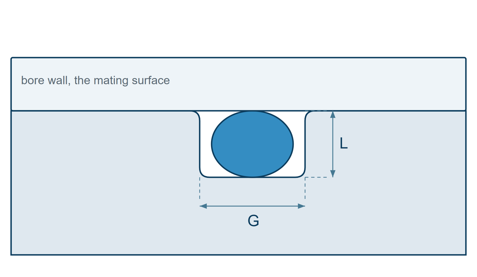
- L gland depth
- mating surface to groove bottom. Squeeze = (CS − L) ÷ CS.
- G groove width
- sized for the ring volume plus the free space it swells into.
- R corner radius
- a sharp corner on the pressure side cuts the ring during cycling.
- E clearance
- the gap between the two metal parts, drawn enlarged. The ring must not be pushed into it.
A radial gland in section. The ring is compressed from CS to L, and the space left in G is what it has to swell into.
Groove check
Works in millimetres, nominal cross section
Leave the two boxes empty to read the band you should machine. Fill is calculated from the cross-section area of the ring against the groove area, which assumes the groove is rectangular with a square bottom.
Recommended Groove Dimensions For AS568 Cross Sections
The three tables below are the gland dimensions published for AS568 cross sections, converted to millimetres. Most seal catalogues print the same figures, so they can be checked against the one on your shelf. Depth and width are bands rather than single figures, because the ring carries tolerance and so does the groove.
Static radial gland: piston or rod, no movement
| AS568 series | CS (mm) | Gland depth L (mm) | Squeeze | Groove width G (mm) | Corner radius (mm) | Clearance E (mm) |
|---|---|---|---|---|---|---|
| -0XX (004-050) | 1.78 | 1.27 to 1.32 | 22 to 32 % | 2.36 to 2.49 | 0.13 to 0.38 | 0.05 to 0.13 |
| -1XX (102-178) | 2.62 | 2.06 to 2.11 | 17 to 24 % | 3.56 to 3.68 | 0.13 to 0.38 | 0.05 to 0.13 |
| -2XX (201-284) | 3.53 | 2.82 to 2.87 | 16 to 23 % | 4.75 to 4.88 | 0.25 to 0.64 | 0.08 to 0.15 |
| -3XX (309-395) | 5.33 | 4.32 to 4.39 | 15 to 21 % | 7.14 to 7.26 | 0.51 to 0.89 | 0.08 to 0.15 |
| -4XX (425-475) | 6.99 | 5.74 to 5.82 | 15 to 20 % | 9.52 to 9.65 | 0.51 to 0.89 | 0.10 to 0.18 |
For industrial static seals to about 100 bar without a back-up ring. Face-type static seals use the face table below, where there is no gap for the ring to extrude into.
Reciprocating gland: rod or piston that moves
| AS568 series | CS (mm) | Gland depth L (mm) | Squeeze | Groove width G (mm) | Corner radius (mm) | Clearance E (mm) |
|---|---|---|---|---|---|---|
| -0XX (004-050) | 1.78 | 1.40 to 1.45 | 15 to 25 % | 2.36 to 2.49 | 0.13 to 0.38 | 0.10 max |
| -1XX (102-178) | 2.62 | 2.24 to 2.29 | 10 to 17 % | 3.56 to 3.68 | 0.13 to 0.38 | 0.13 max |
| -2XX (201-284) | 3.53 | 3.07 to 3.12 | 9 to 16 % | 4.75 to 4.88 | 0.25 to 0.64 | 0.15 max |
| -3XX (309-395) | 5.33 | 4.70 to 4.78 | 8 to 14 % | 7.14 to 7.26 | 0.51 to 0.89 | 0.15 max |
| -4XX (425-475) | 6.99 | 6.02 to 6.10 | 11 to 16 % | 9.52 to 9.65 | 0.51 to 0.89 | 0.18 max |
The groove is deeper than the static one by 0.1 to 0.3 mm. That is deliberate: less squeeze means less friction and a longer life, and the clearance figure is tighter because a moving ring works the gap harder.
Face seal gland: flange, axial, static
| AS568 series | CS (mm) | Gland depth L (mm) | Squeeze | Groove width, liquids (mm) | Groove width, vacuum (mm) | Corner radius (mm) |
|---|---|---|---|---|---|---|
| -0XX (004-050) | 1.78 | 1.27 to 1.37 | 19 to 32 % | 2.57 to 2.72 | 2.13 to 2.26 | 0.13 to 0.38 |
| -1XX (102-178) | 2.62 | 1.88 to 2.03 | 20 to 30 % | 3.45 to 3.61 | 3.05 to 3.17 | 0.13 to 0.38 |
| -2XX (201-284) | 3.53 | 2.57 to 2.72 | 20 to 30 % | 4.50 to 4.75 | 4.01 to 4.17 | 0.25 to 0.64 |
| -3XX (309-395) | 5.33 | 3.86 to 4.11 | 21 to 30 % | 6.86 to 7.37 | 6.07 to 6.20 | 0.51 to 0.89 |
| -4XX (425-475) | 6.99 | 5.11 to 5.36 | 21 to 29 % | 8.69 to 9.19 | 7.85 to 7.98 | 0.51 to 0.89 |
The narrower vacuum column is not a different groove, it is the same groove for a joint that sees vacuum or gas instead of liquid: less width raises the fill, which is what holds a gas seal. Internal pressure wants the groove outside diameter sized to the ring outside diameter, external pressure and vacuum want the inside diameter sized to the ring inside diameter, so the ring is pushed onto the wall that is doing the sealing.
Choosing The Ring That Fits The Groove
Groove dimensions decide the seal, but only if the ring that goes into the groove has the cross section you designed around. Three things move that.
Stretch. A ring fitted over a piston or into a rod gland is stretched to get there. Past about 5 % stretch the cross section thins where it is stretched, the squeeze you calculated is no longer there, and the ring takes a set at that thinner section. Pick the inside diameter so the stretch stays under 5 %, and prefer the next size up over a stretched fit.
Cross-section tolerance. A 3.53 mm cord is supplied at 3.53 ± 0.10 mm on the standard sizes, and up to ± 0.15 mm on the larger ones. That is 3 % of the squeeze you were counting on, in either direction, on top of the groove tolerance, which is why the tables give a band and the checker prints the range across the band.
Compound swell. An NBR ring in an aromatic solvent can gain 15 % in volume, and a volume gain of 15 % at 80 % fill is a ring with nowhere to go. Where the medium is known to swell the compound, aim at the lower half of the fill band rather than the middle. The
material pages carry the swell behaviour of the five common compounds.
When A Back-Up Ring Is Needed
A back-up ring is a hard washer, usually PTFE or a hard elastomer, that sits on the low-pressure side of the O-ring and closes the clearance the rubber would otherwise extrude into. The rule we work to:
- Above about 100 bar (1500 psi) with a soft compound, one back-up ring on the low-pressure side.
- Above about 250 bar, two back-up rings, one either side, or a 90 Shore A compound in the same groove.
- Any pressure where the measured clearance is wider than the band in the table: fit a back-up ring, or reduce the gap.
- Vacuum service: the ring is pushed the other way, and the narrower groove width in the face table is the one to use.
Fitting a back-up ring means widening the groove, roughly by one back-up ring thickness, so it is worth deciding before the part is machined rather than after. The
back-up ring range covers the standard sections; a groove that cannot be widened is a case for a harder compound instead.
What These Numbers Do Not Cover
The tables say nothing about the four things that fail most often in service, so they are worth saying here.
- Surface finish. A groove floor turned to a coarse finish gives the medium a path under the ring. A static gland wants a fine finish on the sealing faces, not a polished one everywhere.
- Eccentricity and runout. A bore that is out of round squeezes one side of the ring more than the other. The average looks right on the drawing and the tight side fails.
- Assembly damage. A sharp lead-in or a burr on the groove edge cuts the ring on the way in. The seal then leaks from a defect that never appears on any inspection sheet.
- Temperature and cycling. Squeeze at 23 °C is not squeeze at 120 °C. A compound with a high compression set relaxes out of the groove, and a joint that held on the bench weeps after a week at temperature.
These are the reasons we ask for the drawing and the duty rather than the size alone. A groove that passes the checker can still fail on finish; a groove outside the band can sometimes be saved by a compound change. Both are things we would rather say before the part is cut.
Questions We Get About Grooves
My groove is 0.20 mm deeper than the table. Can I use a thicker ring?
Sometimes. The next cross section up restores the squeeze, but it also raises the fill, and a ring that fills 95 % of the groove will extrude. If the width is generous it can work, and if it is not, machining 0.20 mm off the depth is cheaper than a special cross section. Send the groove and the quantity and we will price both.
Do I have to machine to the middle of the band?
The band is the tolerance, so any figure inside it is a valid design. What matters is the stack: if the groove is machined deep and the ring arrives at the low end of its tolerance, the two add up. Holding depth and width in the same direction as the mating part keeps the squeeze from swinging.
Can you check a groove drawing for us?
Yes, and there is no charge for it. Send the drawing with the medium, the temperature, the pressure and whether the joint is static or moving, and you get an answer on squeeze, fill, clearance and the compound, not just a price.
Why is a metric groove different from the AS568 figure?
Because the cross sections are different. JIS B 2401 and ISO 3601 metric sizes use their own section series, and their gland tables follow. The
JIS and ISO 3601 pages give the sizes; if the housing is already cut to one of those standards, the groove figures come from that standard, not from the AS568 tables here.
What fill should I aim for with a compound that swells?
The lower half of the band, 60 % to 70 %. Volume swell is measured on a free sample; in a groove the ring cannot grow freely, so a compound that swells 10 % in the medium behaves like a ring 10 % too big for its groove.
Sizes for the ring that goes into the groove are on the
AS568 chart, with the tolerance bands behind them explained in the
tolerance guide. If you would rather work from the groove backwards, send the drawing: we will size the ring to it.